Sunday, November 09, 2014

Long time no see...

Saying that it's been a little while might be bit of an understatement...

I won't bore you with why my life suddenly became much more complicated, but suffice to say that radios took a back seat to everything else for several years.

I have been wanting to get back into it for a while.  While I haven't done much lately, I have slowly started accumulating the pieces so that I can work on the one project that I miss the most - the Philco 70.

I started by giving up on my cabinet.  I still have all of the pieces and parts, but I have decided that I don't have the skill to do it myself.  So I purchased a cabinet from eBay - minus the front panel, and then I purchased a repro front panel to go with it.


If you look closely, you can see that there are some flaws in the veneer, but all things considered, it's solid, and the veneer is not terrible.  

The original thought was just to finish off the front panel, and call it a day.  But the more I look at the cabinet, the less I like the refinishing job that was done.  The dark areas are just too dark, and the sides/top are very blotchy and uneven.  The plan now is to strip it completely and start over.  Today, I glued and clamped one area where the veneer was coming off.  When that's dry, I will break out the Formsby's Refinisher that I have left over, and go to work on this thing.

My inspiration comes from this thread:


I avidly followed this project last year, and it gave me the courage to give it a try on my own cabinet.

So wish me luck, as I dive back in.  I hope I can find the time to get this thing finished off soon.

Wednesday, January 24, 2007

Back to business

Well, it's been a really long time since I've posted anything new here, but mostly that's because the radios have been pretty neglected. I have done a bit of work lately though, so here's a rundown of some of the things I've been up to.

First of all, I finally finished off the Packard Bell clock radio. I had to re-solder an antenna wire that came loose, glue the case back together, and then wet sand and polish it up. It isn't perfect, but it does look pretty good.

Then I decided I needed some more soldering practice, so I recapped the RCA clock radio. I also washed all of the nicotine and other grime off of it, and it looks good and plays well. I still need to do an alignment, and finish cleaning and polishing the case. I also need to touch up the gold paint.

I'll finish it off soon and put some pictures up.

I really want to get moving on the Philco 70 project again. I haven't been able to get ahold of the guy I was going to get my veneer from, so now I think I'll take a ride over to Rockler and see what they have. Meanwhile, I've been practicing with the scroll saw, and I think I'll be able to do a pretty good job on the front panel.

I did decide to finally test the chassis to see if it works. It doesn't. Well, at least not as far as I can tell. When I first fired it up on the dim bulb tester, nothing happened - with a 25 watt bulb (though the bulb did light up). When I bypassed the dim bulb, the transformer vibrated very loudly. I figured out that I had forgotten to put the screws back in that hold the laminations together. Tried it again, and no more vibration. I did get a loud buzz in the speaker, so I figure that's telling me that the filter capacitors are no good.

So I looked at the chassis, and it looks like someone's definitely been inside this radio. The copper caps had been disconnected, and it looks like they were replaced with a pack containing 2 caps, one an 8 mfd, and the other a 16 mfd. As best I can tell, the copper caps were originally 6 mfd each. I have to figure out what to replace these with. Right next to this box is what looks like another, similar pack, but this one is encased in metal (aluminum?). It looks like it's been disconnected too. On the chassis diagram, it looks like this is an original part, but I can't figure out what it is. I'm having a tough time reading the schematics that I downloaded. The Beitmans and Riders are equally difficult.


Since the copper caps had already been disconnected, I decided to remove them from the chassis, so that I could see if I could straighten out the one that is bent. No luck. I'm not really sure what to do with this one. As you can see though, the copper shines up nicely with some Brasso.


So that's the rundown. Slow progress, but I hope to try to sneak in more time to get this project moving again.

Sunday, September 10, 2006

End of summer

Well, I had all kinds of plans for what I wanted to get done over the summer, but most of it didn't happen. What else is new? Most of the time I was just too busy. A couple of times I wanted to get out to the garage and work, but it was just so hot that I couldn't bring myself to go out there. A couple other times I said "heck with it" and went out there anyways - dripping sweat on my work.

I did get a few things done though. I completed the transmitter (which I've already talked about) though I do want to work on some dial-lighting so that I can know when it's on. I completed the battery eliminator for my Silvertone farm radio, and I finally got to play with the scroll saw.

Here's what the transmitter looks like:


While I'm pretty proud about how this project turned out, I do see the limitations of the one-tube design. It does have fairly high distortion at peak volume. I have tried a few different software packages that are supposed to do some of the compression and limiting that professional radio stations use, in order to get a "louder" and more consistent sound with less distortion, but I either I haven't figured out how to properly use them (likely) or they just don't work well. Some day I may try a more elaborate transmitter to see if I can get cleaner sound. This design is also kind of drifty - it does not stay on frequency. Not a big deal if you're using an old radio, but if you try to tune it on a digital radio you find that one day it's on 1200 khz, the next day it's on 1204, or maybe 1202. Even so - it was reasonably easy for this beginner to build, and it does work quite well, considering the simplicity of design - which is more than you can say for the $15 kit that I bought from Electronics Goldmine.

In truth, I'm probably the only one around here who even notices the distortion. I would like to get better range though. At the moment it barely covers my property. A better antenna would probably help, but the other big problem is that we're only a half-block away from an AM station. During the daytime when they're running 50Kw, they really interfere with my transmitter. It's somewhat better at night when they drop to 20Kw. So I probably can't expect very much from any home-brew design - at least not in this neighborhood.

Next on the list is the battery eliminator. This works really well, and fit right into the small priority mail box that I dressed up with a design from Billy Richardson on ARF. You'll notice that I did modify his design to say "A/B" battery instead of just "B". Other than that, it's stock. He did a great job with the artwork. Now that I think about it, I suppose I should have changed it to say 1.5v/90v, but oh well. I'm not going to mess with this one any more.


So back to the Philco 70. I finally got out to the garage a couple of weeks ago to play with the scroll saw. I sketched the pattern from what was left of my original front panel directly onto a piece of masonite. I needed some masonite for another project, and they only sell it in 4 x 8 sheets, so I had them cut it down so that I could use it to practice on. Here's my first try:


Yes, I cut the bottom holes way too large - I forgot that the veneer had smaller holes than the plywood, and traced these holes from the plywood. Next time I'll just drill them with a drill bit. While I think it looks pretty decent for a first-try, I still need more practice. It also looks a lot better in the picture than it does in person. The other thing is that masonite can't really be sanded, so the end-result when cut from plywood, and later sanded to nice smooth curves, should come out pretty nice. I just have to remember to stay INSIDE the lines when cutting. You can always go back over it with sandpaper, but you can never put missing wood back.

I'm going to order the veneer for my 70 soon, and try to get started on the real panel. I'm ordering 2 pieces of the front-panel veneer - just in case.

So I'm making slow progress to be sure, but it's still progress.

Oh yeah, I forgot to mention one more thing. I finally got around to trying out the Philco 89. I plugged it in through my dim-bulb tester, and it actually works pretty well. I think I'll do a recap though before I start trying to use it very much. It also needs a good cleaning and lubing of all of the switches and contacts. The dial is pretty dirty too, but I need to be careful about that. The 70 is first in line right now, and after that I'll look at the 89.

Thursday, July 06, 2006

Quick update

Well, a few things are going on here. First of all, I picked up the Philco 89 up in Santa Paula. Not a bad drive - it's quite nice up there, and much cooler than it's been here at home. The radio looks pretty much like it does in the picture. I was kind of wondering about the color of the cabinet - having seen the Philco 70 cathedral's original finish, the 89 just didn't look right to me.

Now that I have it, I can tell you that I'm pretty sure that someone has used a furniture refinisher or stripper on this radio. There's no trace of the lacquer that was on it originally, just bare wood. The columns and trim look too light to me, and I'm sure that's because the original finish was a toned lacquer. The veneer areas are still pretty dark. Before I start spraying this radio, I'll probably go over it with some refinisher of my own - it does have some stains that I think will come out. One of these days we'll get around to working on that.

I haven't even plugged this radio in, but I might try it on my dim-bulb / isolation transformer setup when I get a chance. The seller said it makes static. We'll see what happens when I hook some wire to the antenna terminal.

I've had a chance to play with the transmitter a lot. It works pretty well around the house, but the coverage is kind of spotty. A lot of this is probably attributable to my location right around the block from KSPN, a 50Kw powerhouse. I'm pretty sure I'd get much better results if I were in a different location. Even so, it does work well. I'd love to find some freeware scheduling software so that I could play different playlists at different times of the day, but I haven't found anything yet. The best I could do is Rivendell, which looks like a dynamite package, but it's really overkill for what I want to do, and it's Linux-only, so I'd either need to dedicate another computer, or run it in a vmware session. Seems like a lot of resources to dedicate for something like this, even though it is pretty cool.

As for the Philco 70, Mike T found me a scroll saw at a neighbor's garage sale for $10, so I'm going to have some fun with that. We'll see if I can reconstruct the front panel. One way or another I have a new toy to play with, so it's all good.

Now to just find the time to play with these toys...

Friday, June 30, 2006

Another radio!

Time for an update!

I've spent a lot of time recently, collecting parts for my current projects, the battery eliminator and AM transmitter. I just finished the transmitter, and last night I fired it up for the first time. Amazing! It actually worked! Huge thanks to Bob, VE1ARN, who generously sent me a tube and socket for free.

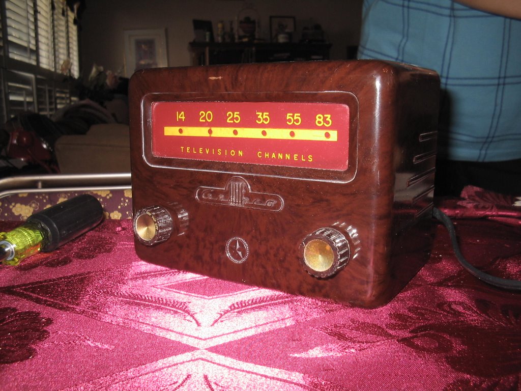
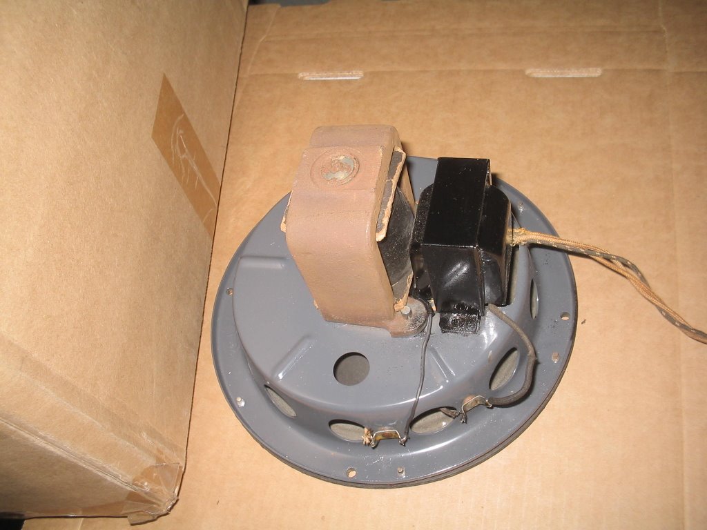
This is a really simple design, that was put together by Syl.

I modified it based on some suggestions from Mike T. The following is an "as-built" schematic. This reflects a different power supply. The Granco UHF tuner that supplied the chassis had the transformer I need. It also has a really nice bakelite case that polished up beautifully with a rag and some Brasso. This modified schematic uses a voltage doubler, to take the voltage up from the standard 180-something, to about 385, which then gets dropped back down to about 275, which is just short of the max allowed by the 6BM8 tube. Hopefully I will get better range than I would with the standard 180.

This is an interesting design. It's really simple, but not "frequency stable" by a long-shot. Everything you do changes the frequency. You can modify the coils or caps, but even putting your hand near it will pull it off-frequency. I had some fun with this effect last night. I put my radio on SSB, and tuned it to the transmitter's frequency. This produced a tone, from the beating between the transmitter's carrier and the BFO of the radio. I was using a 3' whip antenna on the transmitter. If I brought my hand near the antenna, it caused the pitch of the het to change. Waving your hand around, you could get some pretty cool effects. A lot like a Theremin.

Anyhow, the frequency of this transmitter varies based on the antenna you use. So with the whip, I was around 1200 Khz. With a hunk of wire, it was closer to 1130, but when I hooked it to a spare pair in my phone jack, it went way down to 994 Khz. One thing I forgot to do - the original schematic has a fixed 20pf mica cap at C10. I need to change that to a variable, so that I can have some frequency adjustability (apart from what I get just being near the transmitter). Once I get my antenna built, I will take a few turns of wire off the primary of the oscillator coil, so that I can tune it to a more open frequency. My son is already looking forward to being a DJ!

I finally have all of the parts I needed for the battery eliminator. My parts order got lost in the mail, and it took 6 weeks to get it replaced. But everything is here now, and when i get a chance, I will put that together. I'm going to put it inside a box with this design. I know it's not truly authentic, since my battery eliminator will be an A/B supply, not just a "B" like this one, but I think I should be able to modify it to add connectors for the "A" supply. And it will look really cool.

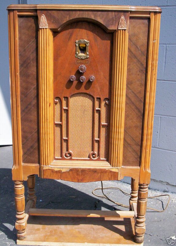
So now, you've read all this stuff, and you're wondering: What about the new radio mentioned in the title? Well, the wait is over. Check this out:


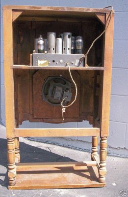
This is a Philco 89 console. Aside from a ding in one of the upper columns, and the veneer on the lower middle front, it looks to be in really good shape. These are the eBay pictures. I hope to have some more once I've picked up the radio. At the moment my son has my camera with him on a backpacking trip, so it will be a little while before I can get any pictures to put up here. I promise I'll post some pictures of the transmitter too - I'm pretty proud of how it came out, both in performance and looks.

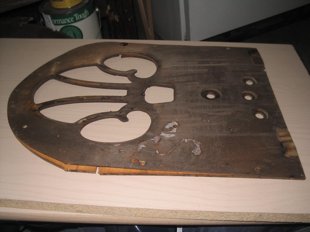
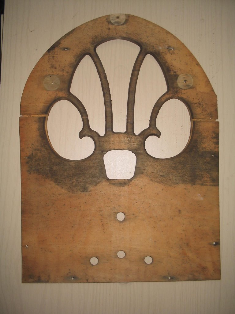
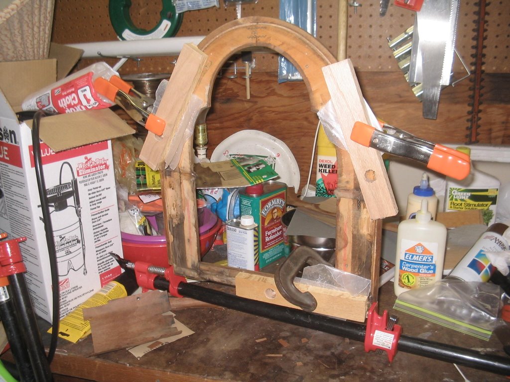
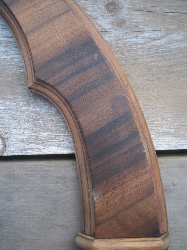
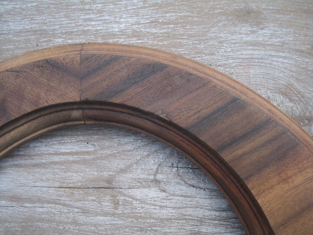
Lastly, I guess I should update the status of the Philco 70. Not much to report there, except that a couple of weeks ago I found out that someone was giving away a Ryobi scrollsaw and bandsaw. Free! Perfect for my non-existent budget! Unfortunately I was just a bit too late, and someone else got it before I did. Bummer.

I'd love to get a scrollsaw - both for the Philco 70 project, and to play around with other neat things. The problem is that I have such limited time, that I really can't justify spending the money on it right now, since it probably won't get much use. So instead, I went to Home Depot and bought a coping saw, some extra blades, and a piece of 1/4" plywood. I'm going to try to make the front panel with these. The plywood was only $3, so if I mess up, I can just start again. If I can get a reasonable facsimile of the front panel made, then I'll invest in some veneer.

It's summer now, which means no homework to help with, and more flexible bedtimes for everyone. So I hope to be able to spend a bit more time on my radios. I've already succeeded with the transmitter, so I'm hopeful that I will be able to do the same with the other projects. I certainly have learned a lot by building the transmitter.

Thursday, June 01, 2006

Now look at this fine mess I've gotten myself into...

Well, things seem to only go from bad to worse with the Philco 70. Here's what the front panel looks like now:


The last time I posted, I showed how the previously nice & flat panel had warped badly. I wet it down and clamped it. That helped, but not enough. So I did it again. This time it not only stayed warped, but as it dried, the various layers dried at different rates. This caused the front part of the panel to crack and split. I think it's pretty well shot now.

So I figure I have two choices. Buy a whole new repro cabinet (or junker cabinet that's in better shape than mine), or figure out how to make one myself. Buying one is expensive, and I'm still not ready to give up.

Even so, I'm not sure how I'm going to do this. It doesn't look like it would be that hard - just trace the pattern onto a new piece of wood, cut it out with a scrollsaw or something similar, and put some veneer over it. Of course things always seem easy until you've actually tried to do it.

I guess we'll just have to see what I can do.

In the meantime, I've got two other smaller projects I'm trying to work on. First is a battery eliminator for my Silvertone farm radio. I've got almost all of the parts together for that - I'm just waiting on one more order to arrive. The other is an AM transmitter. As much as I like AM radio, there really isn't much there I want to listen to. So if I build my own transmitter then I can listen to the stuff I like to listen to. And best of all, there won't be any commercials :-)

I've got most of the parts for this one, but I am waiting on a few more items. I'm planning to use a slightly modified version of Syl's 6BM8 design. The mods came from tubbytwo, who used a voltage doubler in the power supply circuit. The idea being that since the tube can handle a lot more than the 160v in the original design, we can get better performance with little additional work or cost. We shall see how that goes.

Anyhow, the shell of this project began life as a Granco UHF tuner. I will be gutting it soon, and will hopefully get this project going as soon as more of the parts arrive. Originally, I bought an Astatic TV signal booster for this purpose, but once it arrived, I realized that the transformer did not have the high voltage secondary winding that I needed for this project. I suppose I could have made it work using the high-voltage circuit that it already had, but similar to an All-American-Five design, it has a hot chassis. I really don't want anything with a hot chassis around my house. Not with a very curious 2-year-old wandering around. For a few bucks more I got the Granco, and now I'm good to go.

So that's where I'm at. I have had almost no time recently to work on this stuff - just a few minutes here and there. Hopefully this will change soon (haven't I said this before?).

Sunday, April 30, 2006

Long time no see...

Well, it's been a while. I took a long break for the Passover holiday, but I have tried to get little stuff done since then. Here's what the speaker now looks like. I couldn't think of a good way to clean the magnet frame, and I didn't want to paint it, so I left it as-is. I don't think it looks too bad as it is, even if it does look a bit ratty compared to the fresh paint on the surrounding parts.


I did have a bit of a mishap. I had left the front panel sitting in a nice safe place, but imagine my surprise when I saw what had happened in the last couple of weeks:


Yes, it curled pretty badly. I guess the steam that I had used in getting the veneer off must have penetrated the plywood pretty well. When I left it just sitting, it dried unevenly, and got warped. I wetted it down well, and clamped it between a couple of boards. I'll have to leave it for at least a couple of weeks to see if I can get it straight again.

The following picture shows all of the clamping I've had to do to finish repairing the missing veneer. This repair was on the back side - there are really narrow strips of veneer along the outer edge, that will show when it's re-assembled. I tried cutting small pieces of veneer and gluing them in place, but the scraps that I'm using are very brittle, and I didn't have much luck. Most of the patches came off again, so I decided to just use wood putty instead. I figure that this part will get a pretty heavy coat of toner, so you probably won't notice the difference. I also used some dark walnut stain just to even things out. It looks decent now.


Here's what the front arch looks like now. Not bad from the long view, but there are some imperfections that I'm concerned about.


See that little spot in the picture below? That's some wood putty that I used to fill a gouge in the veneer. Even with stain, it stands out pretty well. After all of the patching that I did to the veneer on this piece (which incidentally looks pretty good to me), I hope I can do something with these spots.


I went to Harbor Freight and got the clamps that I need (unfortunately they were not on sale, so I paid $7 instead of $4. Still a deal). So as soon as I'm done fixing up the front arch, I hope to attach the flexible plywood body.

In the meantime, I'm kind of itching to start on the chassis. Unfortunately my workbench is a disaster, and I need to clean it up to make room to work. This is a must if I'm going to have the room to work on the chassis and the cabinet at the same time. That's it for now.

On a slightly different subject, I call your attention to the link on the right for "Elements of Radio Servicing". This is a really old book that's supposed to be one of the best on the subject. I guess it doesn't matter much that it was written in the 40's, as long as the radio you're working on is older than that - or uses the superhet design that is common to so many radios. In any case, there it is if you want it. I plan to read it in my spare time. Whenever that might be.